Case Histories
Following are some examples of products and instrumentation that we have developed for clients to meet their unique specifications and requirements that could not be met using off-the-shelf commercial equipment. These examples also illustrate the range of applications, from the R&D lab to the production floor, supported by Design & Test Technology.
Medical - Dental Laser System
The control electronics for a portable dental laser system was designed, built and programmed by Design & Test Technology.
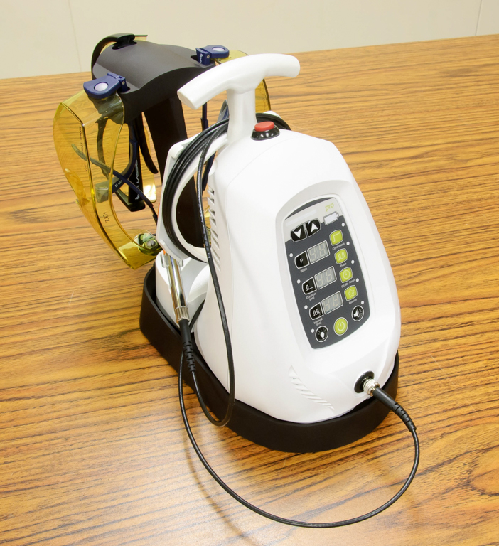
Battery Operated Portable Dental Laser System
This portable system is powered by an internal 3-cell Lithium-ion battery and provides both pulsed and CW laser output at user-selectable power and duty cyce settings. We designed and programmed the system controller and wireless foot switch components of this system as well as providing the final integration, calibration, and system testing. This system supports diagnostics, calibration and firmware upgrades through its USB port and supports both wired and wireless foot switch control.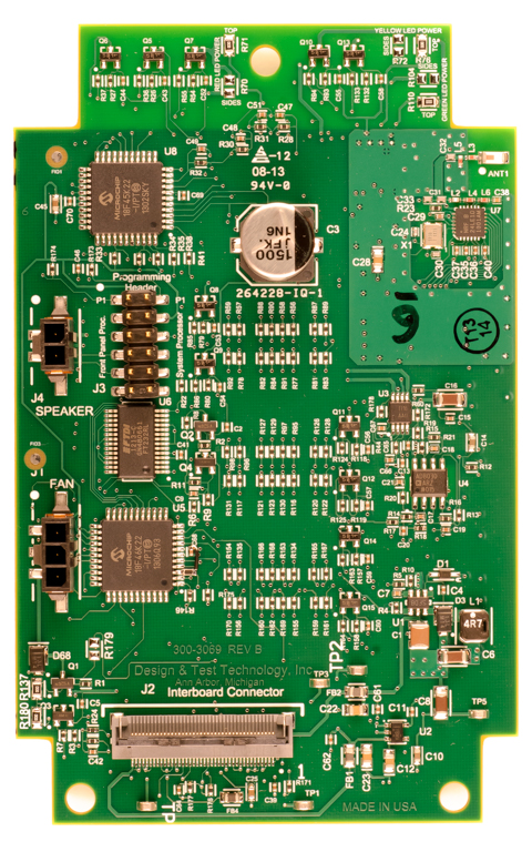
Dental Laser System Controller Board
System controller board for the portable, battery operated dental laser system. This board controls the laser driver and provides a user interface through its front panel keyboard and display, as well as a wireless interface to an external foot switch and a USB interface to a diagnostic port for calibration and diagnostics. This board incorporates three embedded processors: a PIC18 for overall system control, a second PIC18 for front panel controls, displays, and audio, and a Nordic Semiconductor SoC for the wireless foot switch interface.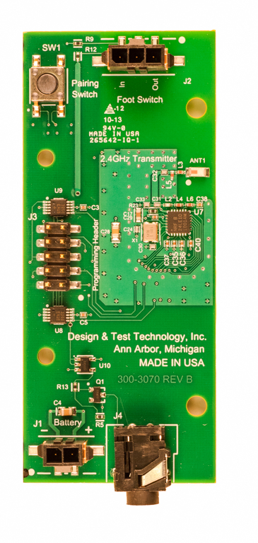
Wireless Foot Switch
This board provides a 2.4 GHz ISM interface to control the portable dental laser system. It uses a Nordic Semiconductor SoC chip that includes both the wireless transceiver and an 8051-compatible microprocessor to control all functions. It typically operates for 6 months using two AA batteries and provides two LED outputs that indicate communication and battery status.MeasureBoard Series
The MeasureBoard instrument, which was designed, built and programmed by Design & Test Technology, has tracked the state-of-the-art in hardware technology since its first release in 1996.
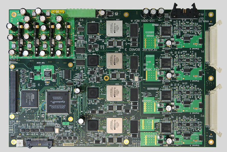
DSP-based Measurement Board - Gen 3
Digital Signal Processing based measurement board for R&D or production testing of magnetic heads and media. This third generation board provides four independent measurement channels with each channel having a 200MSPS ADC, write signal generator consisting of a RAM-based digital pattern generator and a programmable PLL-based clock supporting clock rates up to 770 MHz, a programmable digital bandpass filter and an FPGA for implementing general-purpose, real-time data processing functions.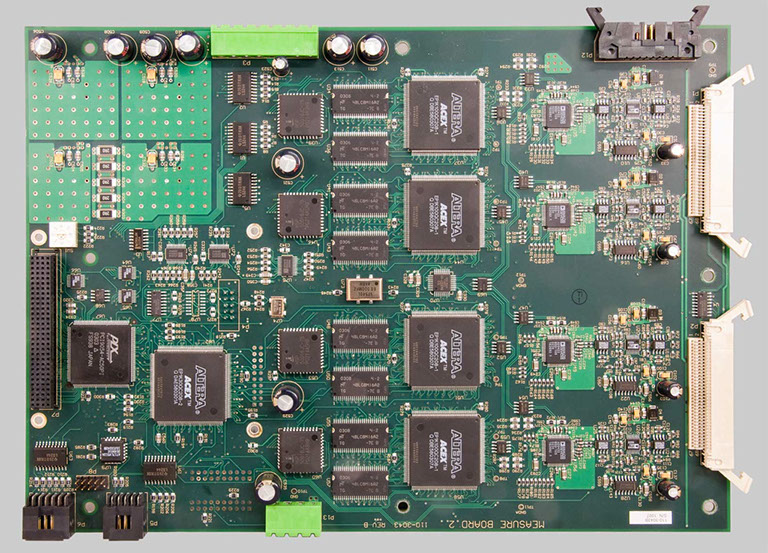
DSP-based Measurement Board - Gen 2
Digital Signal Processing based measurement board for R&D or production testing of magnetic heads and media. This second generation board provided four measurement channels with 80MSPS ADCs, programmable write signal generators with programmable PLL-based clock, programmable digital bandpass filters and four separate FPGAs for implementing general-purpose, real-time data processing.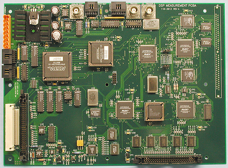
DSP-based Measurement Board - Gen 1
Digital Signal Processing based measurement board for R&D or production testing of magnetic heads and media. This first generation board provided one measurement channel consisting of a 40MSPS ADC to measure the read head input signal, a programmable write signal generator, a programmable digital bandpass filter, and a general-purpose data processing section implemented in four FPGAs.Sensors
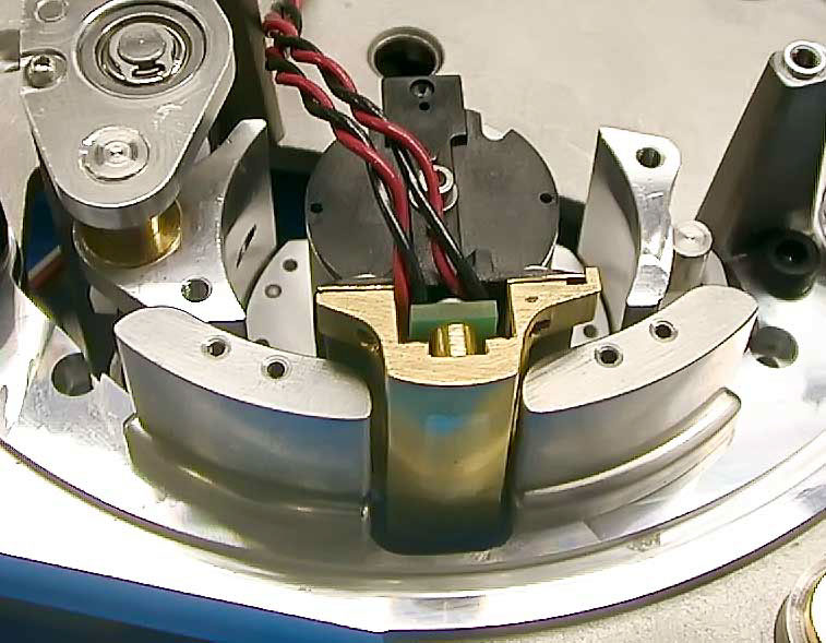
Non-contact Tape Tension Sensor
A unique non-contact method for measuring the tension in a 1/2 inch web of magnetic tape was implemented by measuring the pressure in the air-bearing between the tape and the sensor assembly through a 0.010 inch hole in the center of the sensor.
The simulated head is moved vertically to measure the tension across the width of the tape. Located directly behind the 0.010" hole is a tightly coupled pressure transducer mounted on a small PCB with its low-noise amplifier and buffer.
PCB Design
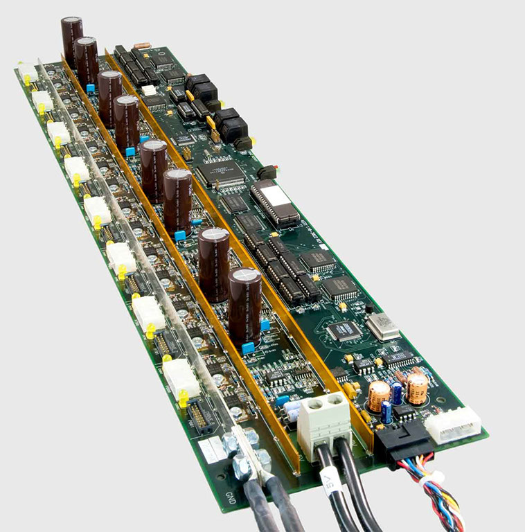
8-Channel Serial Exerciser Controller Board
This printed circuit board assembly is an older example of power distribution and serial control/monitor signals multiplexed to eight LTO drives. It is used for extended production test.
The board will switch up to 5 Amp at 5V and 4 Amp at 12V to each drive and monitor the current with high side sensors. For a meaningful test environment, the average voltage drop at the far end of buses had to be less than 0.050V. This was achieved with bus bars and parallel 4 oz. wide copper traces.
Magnetic Recording
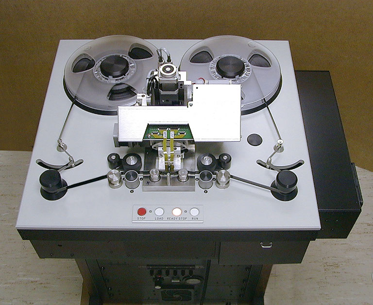
LTO Head-Media Prototype Test System
This is an example of web control using a dual-capstan tape transport in order to control both tape speed and tension at the read/write head. This Instrument is a Parametric head/media test system used for Lab testing of LTO heads and media. It also included precision capstan motor encoders to precisely monitor position and a two-axis head positioner to control head vertical position and rotation under program control.
After an extended 8 hour test shuffling the tape 50 meters in forward and reverse directions at 1 meter/second, the head could be accurately positioned to the original position within 100 microns.
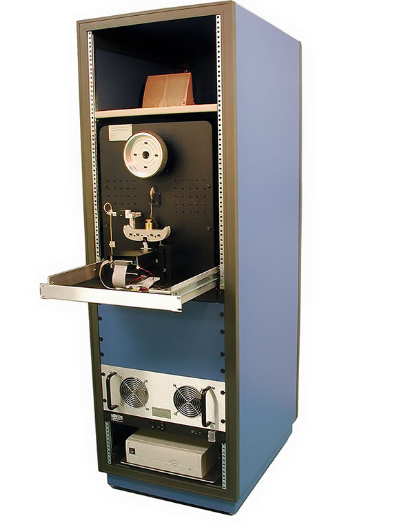
8-Channel Parametric Tape Test System
This is an implementation of the MeasureBoard Instrument in a loop tester. It measures the durability of a very thin web of tape material.
It cycles a loop of 1/2 inch wide tape through a tape-head interface to monitor the parametric measurements of magnetic tape in an environment of rapidly accelerated wear.
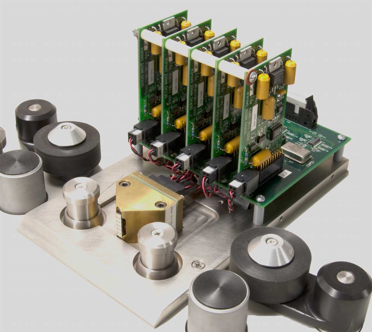
LTO Servo Write Head Driver
LTO servo write head driver using our patented head and driver configuration to provide improved high speed write performance.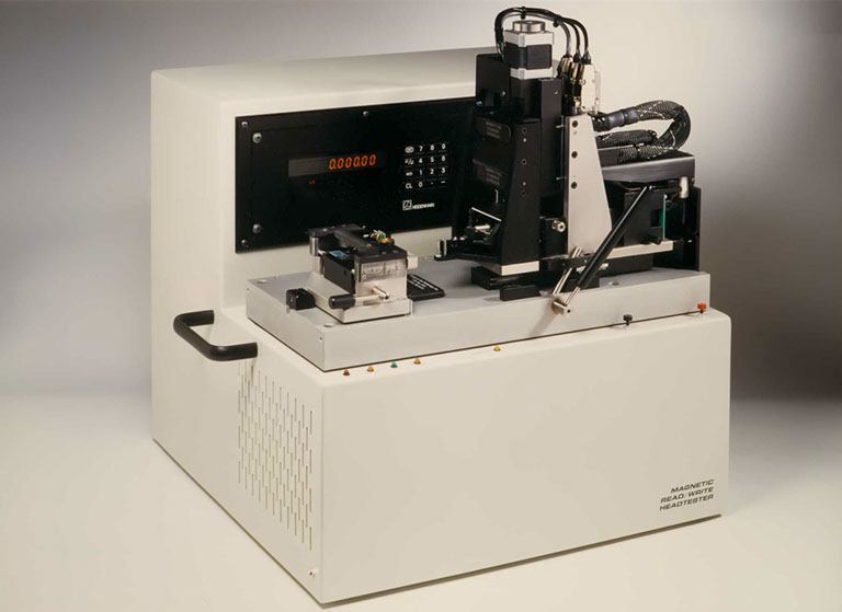
DSP-based Travan Head-Media Test System
Parametric head/media test system used for high-volume Lab testing and QA inspection of Travan heads and media. It included a precision capstan motor encoder and a vertical positioner to precisely control the tape and head positions under program control.
Overall tolerance stackup between the tape cartridge, on the left, and the head assembly was maintained at less than +/- 0.0005 inch. A Heidenhein optical gage monitored vertical movement to 0.5 micron. This enabled high resolution amplitude profiles to be taken across the width of a single track (68 micron).
Travan Drive Test System
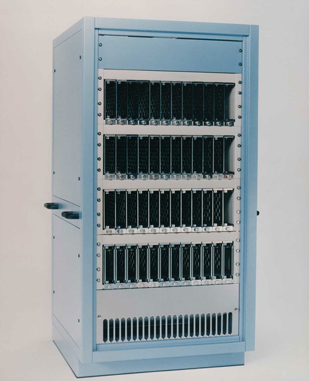
Production test system for high-volume functional and parametric testing of Travan tape drives. Each unit included 24 independent test modules that were controlled by a single host computer. Each test module could be configured to test floppy, ATAPI, or SCSI interfaced drives. The floppy interface modules included window margin analysis hardware.
These very rugged cabinets were designed to follow the production line as it was moved from California, to Japan, and - finally - to Singapore. The power supplies had extensive filtering and protection against the very high number of lightning strikes common to Singapore weather.
Tape Servo Writing Systems
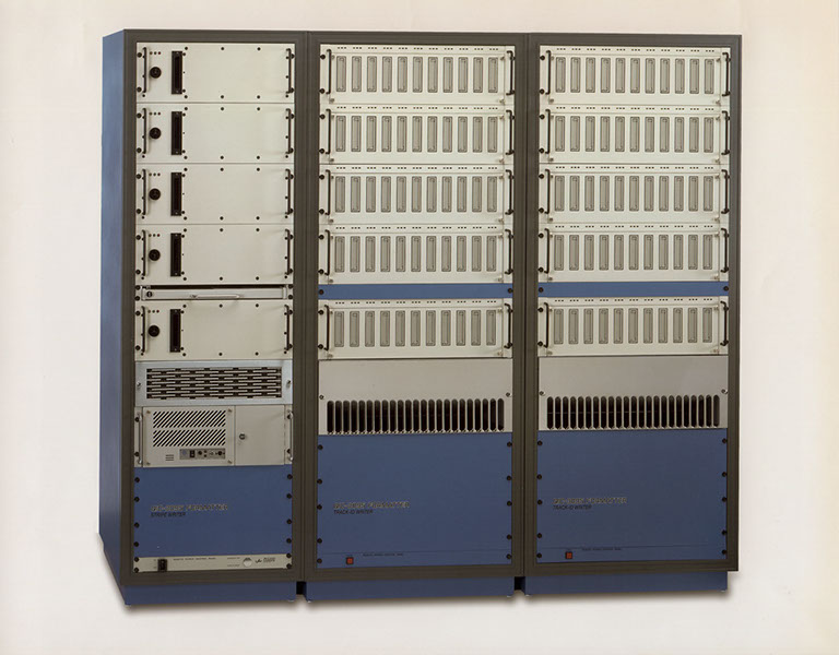
Travan Tape Servo/Track ID Writer System
Automated system for servo and track ID writing of Travan-4 and Travan-5 tape cartridges used for all Travan tape production. Each system contains 5 servo writers and 120 track ID writer slots which are all controlled by a single host computer (not shown). Twenty of these 3-bay units were built over a 10 year period. All Travan-4 and Travan-5 tapes manufactured by Imation were servo-written with this equipment.Industrial Test Systems
Low Voltage Control Box Test System
Automated tester for production line testing of the low voltage control box of a bowling pin setter. It provided about 30 static and dynamic signal stimulus inputs and monitored over 200 outputs from relays and actuators. It also provided controlled 3-phase, 220V output to device under test.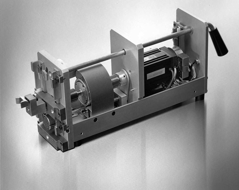
RDLA Probe Test Module
This piece of test equipment was used in off-line test of automotive Rotary Door Lock Actuators. 24 RDLAs were mounted in a temperature chamber and, once per shift, this tester was moved from module to module performing parametric test.
The system included a rotary torque sensor with two calibration curves: 0-20 oz-in for measuring the torque required to operate the RDLA with a key, and 0-200 oz-in for measuring torque available to activate the door locks.

